
Object Storage - What Is It? (1/3)
In this series of articles, we will start with a wide description of the Object Storage technology currently in production at Scaleway.

In the previous articles, we published a general overview of Object Storage as well as the logical workflow of get and put operations. In this article, we will go through the infrastructure design on which our object storage service runs.
The first challenge was to find the right balance between the network, CPUs and IOPS to optimize our investment. It was also necessary to estimate the power consumption of this infrastructure to meet our physical infrastructure constraints.
As a result, we used many CPUs with low consumption in order to achieve a higher density. On the network level, we used 200 Gb/s per rack.
A typical rack is composed of 38 servers called Storage Pods (SP), headed by
two Load Balancers (LB) and two Top-of-Rack switches (ToR). A storage pod contains 150 TB of capacity and has hot swappable disks.
The ToR are L3 load-balanced on two different routers. This provides under
nominal conditions 200 Gb/s of full duplex bandwidth, and 100 Gb/s in case of failure of one of the components.
Each LB (running HAproxy) is connected to a 100 Gb/s port on each ToR via their 40 Gb/s Network Interface Card (NIC), the links are L2 bonded to provide under nominal conditions 80 Gb/s to each LB.
The storage pods are connected to a 25 Gb/s port on each ToR, via their 10
GBits NIC, the links are L2 bonded to provide under nominal conditions
20 Gb/s to each SP.
Gateways are running with 256GB of RAM and with a connectivity of 100G.
Our booting process is based on PXE servers to have a server configuration totally idempotent. Once an image is started, further configuration is made using Salt.
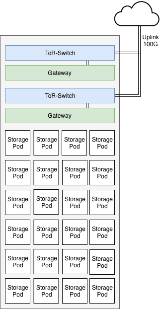
Typical Object Storage Rack
The second challenge we faced is the failure domain. Our goal is to avoid data unavailability caused by a faulty switch, a broken fiber or a rack that might have been disconnected.
This is why all our racks on the object storage are totally redundant at the network level. We have a minimum of two interfaces per server connected to two different switches, with an additional interface for management on a dedicated switch.
We have also established a minimum design of 3 to 5 racks, in order to allow us to tolerate the loss of a rack.
We tuned the density to the maximum of our racks by working with servers providing a capacity of nearly 150TB on only 1U.
We could have chosen servers with 4U providing nearly 1.5PB, but we preferred to limit our failure domain.
We have a capacity of 200Gb/s per rack and we are placed between the exit of the Internet and the rest of our infrastructure, so we are not directly impacted by any outage that could occur on the rest of our products.
Each bay also benefits from two local load-balancers in the rack, each load-balancer is a dual CPU machine, capable of supporting the associated network load.
Each load-balancer has two network interfaces tied together which allows us to tolerate the failure of an interface in a way that is invisible to the software.
All its servers are addressed via a IP ECMP which is declared in zone A of our DNS.
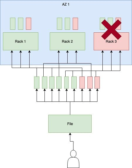
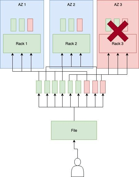
Failure Domain of Availability Zone
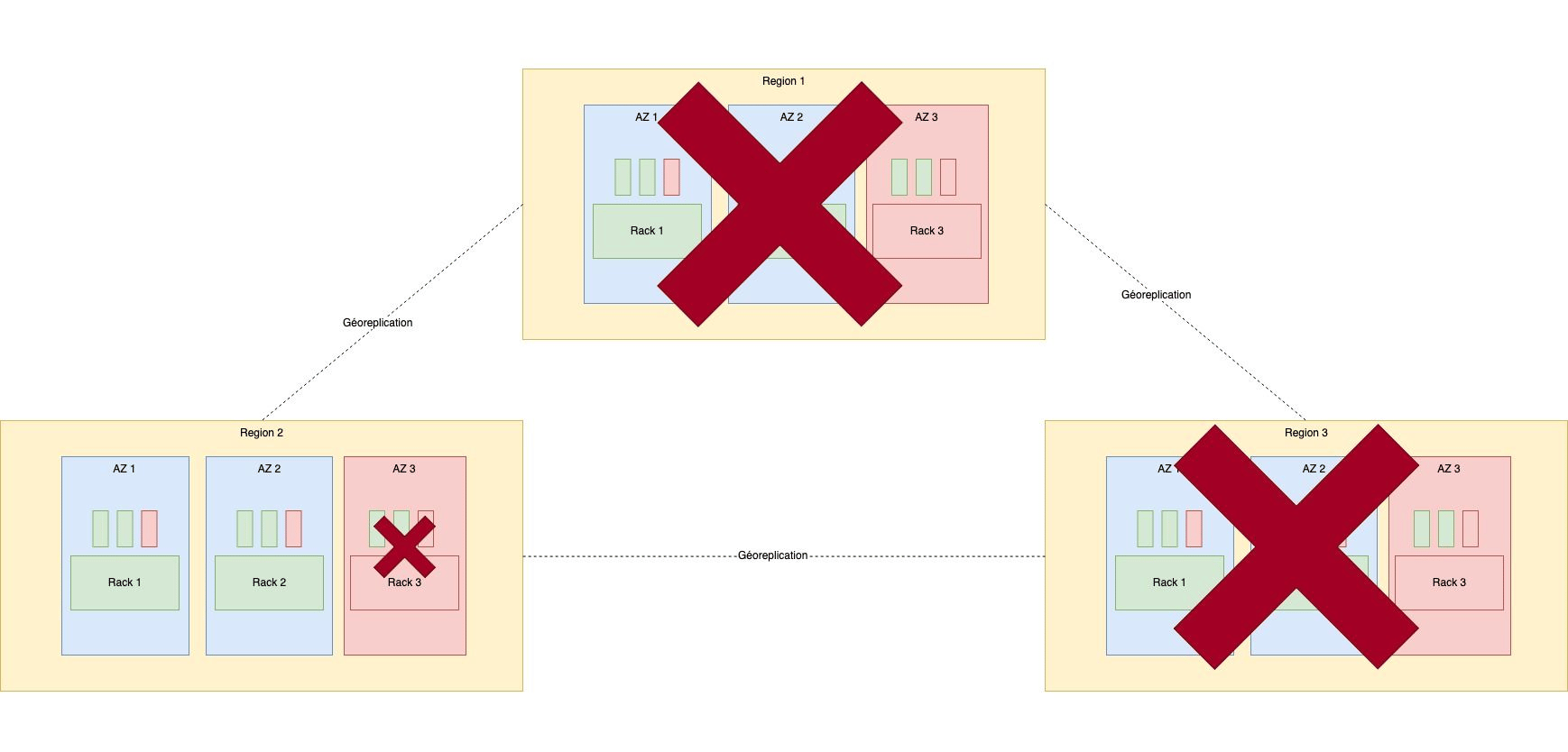
To summarize, below is a reminder of how we mitigate different failures types:
[√] Machine : Distributed design
[√] Switch : Bonding
[√] Drive : Erasure Coding
[√] Twinax/SFP : Double network attachement
[√] LoadBalancer: Dual Load-Balancer per rack
[√] network interface: Double network card
[√] Electricity : Dual electrical feed
[√] Region : We have two regions, the customer can duplicate the data
We monitor the entire cluster on different aspects:
In order to have a reliable billing process, a reliable architecture must be
designed with the following constrains:
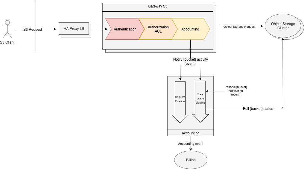
At each request made by a client, the gateway will create an event. This
event will be processed by the Scaleway accounting stack, which will create a billing event, if necessary.
Each Object Storage request received on the gateway generate an accounting event. The accounting system will increments counters which are reseted regularly, and periodically a billing event is generated (for example every 1 million GET Object request).
The basic idea is to pull regularly (e.g. every 15 minutes) the data usage by
each bucket in the cluster. Then regularly (e.g every day) the average data
usage is aggregated by the accounting system and then a billing event is created and sent to the billing system.
The main caveat with this simple architecture is that a frequent data usage
pull might have a very high-performance impact on the cluster. To avoid that, the idea is to pull only the buckets that have changed during a brief time period.
To know if a bucket has changed, the Object Storage Gateway will send an event to the accounting system every time a bucket is modified (PUT Object, DELETE Object...). To avoid any problem with old buckets (buckets that haven't changed in a long time), the system will automatically insert virtual bucket modification events every so often.
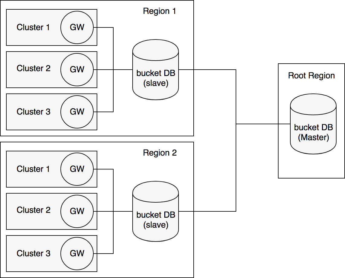
One product requirement is to have a uniqueness of bucket names across all
the clusters in every region. To meet this demand, a central database is populated with the list of every bucket created.
The bucket DB should only be used in 2 scenarios:
GET Bucket location request which returns the region of the bucket.The bucket DB is only contacted by the gateway.
During the design process, the team kept in mind that in the future this
Bucket DB might not only contain the bucket names but also other metadata
such as CORS information.
We use CockroachDB for this database to ensure good replication accross our different regions.
We still have many challenges to face today and tomorrow. We are aware that the confidence in storage products is based on availability as well as durability.
It is the robustness of our infrastructure and our expertise on the subject that will make us earn the trust of our users.
We want to add more reliability mechanisms to ensure that even in the most challenging failure case, the availability of customer data will not be affected.
The Amazon S3 protocol being a standard created in 2007, we need to reach the level of features necessary to help companies in their cloud provider migration.
We need to work on our expansion in several regions to convince customers who are waiting for geo-replication features.
There are also advanced ACLs on buckets which is a very popular feature for our customers.
We are also working to upgrade the rest of our infrastructure to use this technology as well as upgrade some storage products that we already support.
We believe that object storage is one of the core building block of a modern cloud native application architecture.
In this series of article we dived deep into the reasons behind using an object storage, the internal lifecycle of a request and finally how we implement it at Scaleway.
Object storage is ready to use today! Create your first bucket now!

In this series of articles, we will start with a wide description of the Object Storage technology currently in production at Scaleway.

In this article, we will present the internal architecture of Scaleway Object Storage.

We built a whole system on top of Redis to facilitate the setup of a secure cache. The result? A lighter load for your primary database and a secure and smooth automated caching service.